
[ad_1]

This IoT Fall Detection System provides a proactive solution, ideal for those seeking to enhance the safety of loved ones or individuals at risk of falls.
Falls pose a serious risk, particularly for the elderly and those with medical conditions.
With this IoT-based fall detection system, instant notifications on a mobile phone can be received in the event of a fall. This enables a swift response, potentially preventing serious repercussions.
Utilizing a six-axis gyro cum acceleration sensor and a microcontroller, we can detect and measure motion and orientation changes, and with Blynk, a user-friendly interface can be created for receiving notifications and alerts.
The hardware and software implementation, including setting up the MPU6050 sensor and ESP32 microcontroller, configuring the Blynk app, and programming the system using the Arduino IDE, is explained in detail.
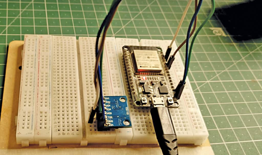
Components used in the IoT Fall Detection System are listed in the bill of materials table below.
| Bill of Materials | |
| Components | Description |
| ESP32 (MOD1) | Microcontroller for programming |
| MPU6050 (MOD2) | 6-axis gyro and acc. sensor |
| Micro USB | |
| Breadboard (for circuit prototyping) | |
| Male-to-male jumper wires | |
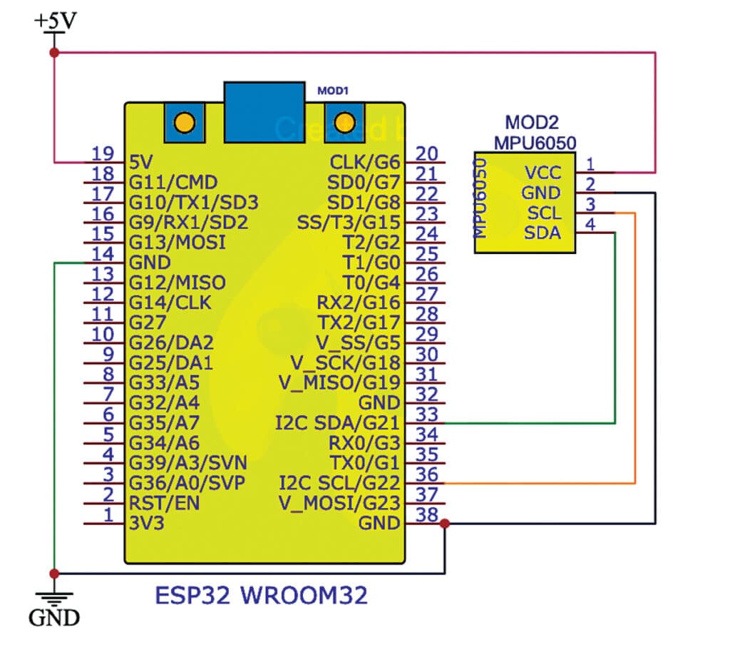
Fall Detection System – Circuit Diagram
The circuit diagram of the IoT fall detection system using MPU6050, ESP32, and Blynk is shown in Fig. 2. It comprises ESP32 microcontroller (MOD1), MPU6050 (MOD2), micro USB cable, breadboard, and a few male-to-male jumpers.
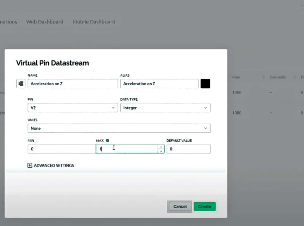
Before coding, set up the Blynk API key and account.
First, create the Blynk account, then create the project template, obtain the authentication token, and note it to use in the code later. Also, add the required libraries.
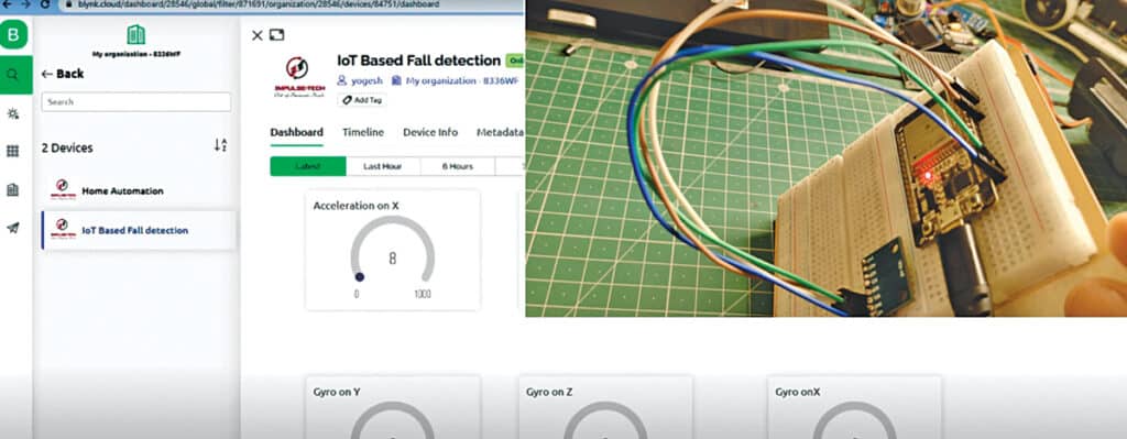
Fig. 3 shows the Blynk dashboard, and Fig. 4 shows how the Blynk setup is done.
IoT-Based Fall Detection System – Code
For code, use the following libraries and install them using the library manager:
WiFi.h: Handles Wi-Fi connectivity on the ESP32.
WiFiClient.h: Used for creating a Wi-Fi client connection.
BlynkSimpleEsp32.h: Enables communication with the Blynk IoT platform on the ESP32.
Adafruit_MPU6050.h: Provides support for the MPU6050 sensor, allowing reading of the data from the sensor.
Adafruit_Sensor.h: Includes sensor event data types and helper functions used with the Adafruit sensor libraries.
Wire.h: For I2C communication, used for connecting and communicating with the MPU6050 sensor.
Ensure these libraries are installed in your Arduino IDE or the platform you are using for project development. A step-by-step coding explanation is given in the code snippet setting Wi-Fi and Blynk token shown in Fig. 5.
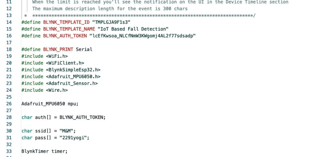
In this section, define the Blynk template ID, name, and authentication token according to your credentials for the Wi-Fi network and authentication token. Include the necessary libraries for Wi-Fi, Blynk, MPU6050 sensor, sensor events, and the Wire library for I2C communication. Fig. 6 shows the code snippet.
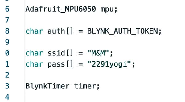
Create an instance of the Adafruit_MPU6050 class for the MPU6050 sensor and define variables for Blynk authentication, Wi-Fi SSID, and password. The BlynkTimer object is used for scheduling tasks. Fig. 7 shows the code snippet for sensor data capturing.
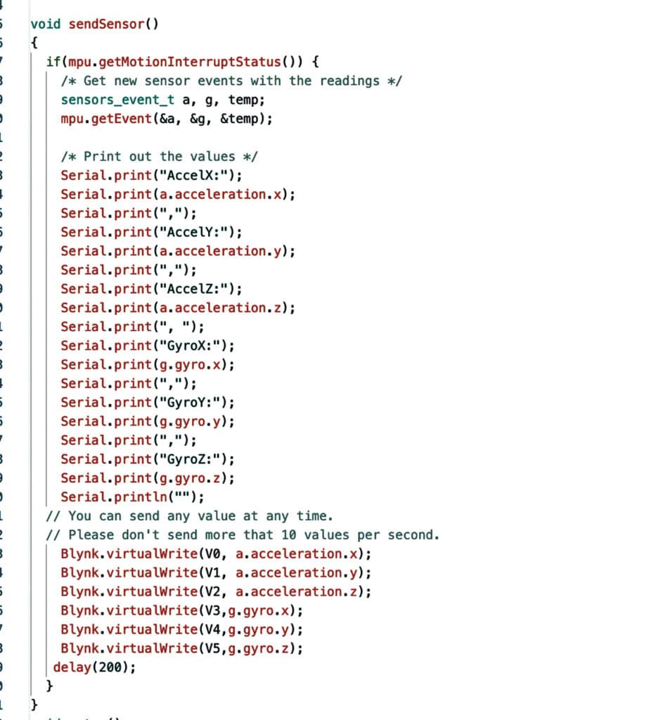
The ‘sendSensor()’ function reads data from the MPU6050 sensor and sends it to the Blynk app. It checks if a motion interrupt has occurred, reads accelerometer and gyroscope data, and sends this data to the Blynk app using virtual pins (V0 to V5). A delay is introduced to limit the data-sending rate. Fig. 8 shows the code snippet for the setup function.
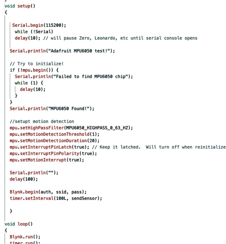
The ‘setup()’ function initializes serial communication, sets up the MPU6050 sensor, configures motion detection settings, and connects to Wi-Fi and the Blynk server using provided authentication credentials.
The ‘sendSensor()’ function is scheduled to run regularly. In the ‘loop()’ function, ‘Blynk.run()’ and ‘timer.run()’ are called to handle Blynk communications and timer-based tasks, respectively.
This code is for an IoT-based fall detection system that uses an ESP32, MPU6050 sensor, and the Blynk platform to monitor and transmit motion and orientation data, making it suitable for fall detection applications.
DIY Fall Detection System – Testing
Connect the sensor according to the circuit diagram shown in Fig. 2, upload the code to the board, and power the device with a USB cable or 5V battery.
Wait for the device to connect to Wi-Fi.
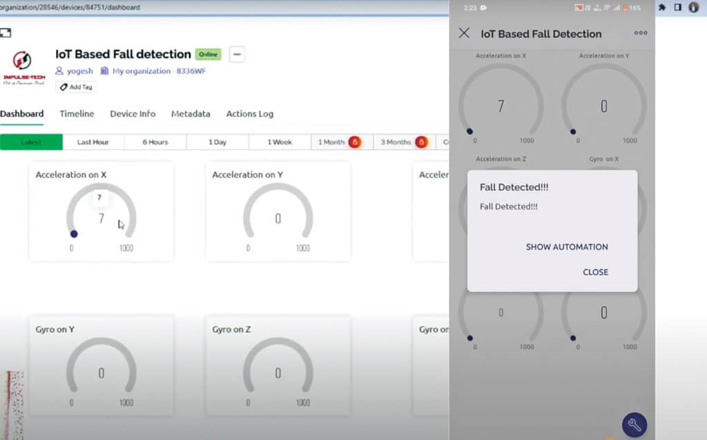
Now make the device fall or change the acceleration of the device rapidly; it detects and displays it on the Blynk dashboard and shows the alert on the phone as shown in Fig. 9.
Yogesh Bawane is a robotics and coding educator, Udemy instructor, curricula developer, YouTuber, edutech enthusiast, and IoT content creator
[ad_2]